Friday, 10 January 2014

Running real code is usually asking for trouble.

Self Portrait
Thanks to Sean, Kevin and the MESS team I've got some real code running. It's quite interesting.

One of the big issues with the TMS1000 is the instruction set is mask programmable. It's not like a 6502 when you know what you are getting or like a Pentium when you know 2 + 2 = 7, you can (I think !) order it with a reorganised instruction set. I kind of reckoned nobody ever bothered, I mean if you did that the development tools wouldn't work.

I've been running BlockBuster on the emulator (It's one of those knock the bricks out of the wall games) . One of the first things it does is display something like 7 ST (a bit like this http://home.comcast.net/~eichler2/microvision/MicroBlockSim.htm).

It sort of works. It displays something, but not what it should.

Looking at the code, I find this (note for people even more pedantic than me - code has been remapped from the LFSR PC to a standard counter PC. If you don't comprehend this this means you are a normal human being).

796   ldx 4          // set X index to 4
797   tma            // Load Memory(4,Y) to accumulator
798   tdo            // put A (pixel data) on output lines to LCD
799   tya            // save Y in A (this is the ptr to the data)
79A   tcy 7          // set Y to 7 (the data clock latch)
79B   rstr           // set data clock (latch 7) to 0
7BC   setr           // set data clock (latch 7) to 1
7BD   tay            // restore the pointer.

which is all very sensible. This should load a nibble into the accumulator (Y points to the pixel data at the start), put it on the LCD data bus and put a pulse on the data clock line to load it into the latches, it preserves the pixel data pointer whilst it does this).

However ....... it doesn't work.  Single stepping this code, it doesn't output the data to the LCD.

Because ... it shouldn't work

The reason it shouldn't work is in the TMS1x00 Programmer Guide.

It says (page 8-12) "The operation of the SETR and RSTR commands is possible for 0<=Y<=15 and 0<=X<=3. And it explicitly says - the X register must be <= 3.

(I note that the Microvision emulation for the TMS1x00 doesn't test this. This might be because they know more than I do, or because they are working from the TMS1000 which doesn't do this test, because X is always 0,1,2 or 3)

A brief perusal of the code above shows X isn't in the range 0-3. It's 4. So , according to the book - it shouldn't work.

Now the code is obviously - to me anyway - doing what it should. It makes logical sense, and it may well work without this test.

Whether the book is wrong (other lists don't mention this X requirement and it does seem a bit pointless !), or the chip is a special one, I don't know. The problem is, of course, if the chip is a special this is an entirely new issue. It doesn't seem to be, what I see of this code makes sense. So I'm going to fix it so it works irrespective of X is and see what happens.

From the challenge view point it doesn't matter as I'm writing a new game not an old one, but if I can get it working reasonably I know my emulation is okay. (If you do nothing it beeps three times to warn you which kinda makes sense). I do have a Microvision so I must see if it actually does this.

The display, we shall see.


Thursday, 9 January 2014

Other MB work

I'm still looking for the Microvision ROMs - hopefully I can get some of the early dumps that some of our technical geniuses have done.  Apparently the MESS Microvision emulation does work - to some extent anyway, and browsing that source my interpretation of the controller and theirs aren't that different.

There's two methods. The TMS1000 patent describes a method of testing the chips by dumping the ROMs serially. It was known this was possible, but not how to do it, but it seems it has been figured out.

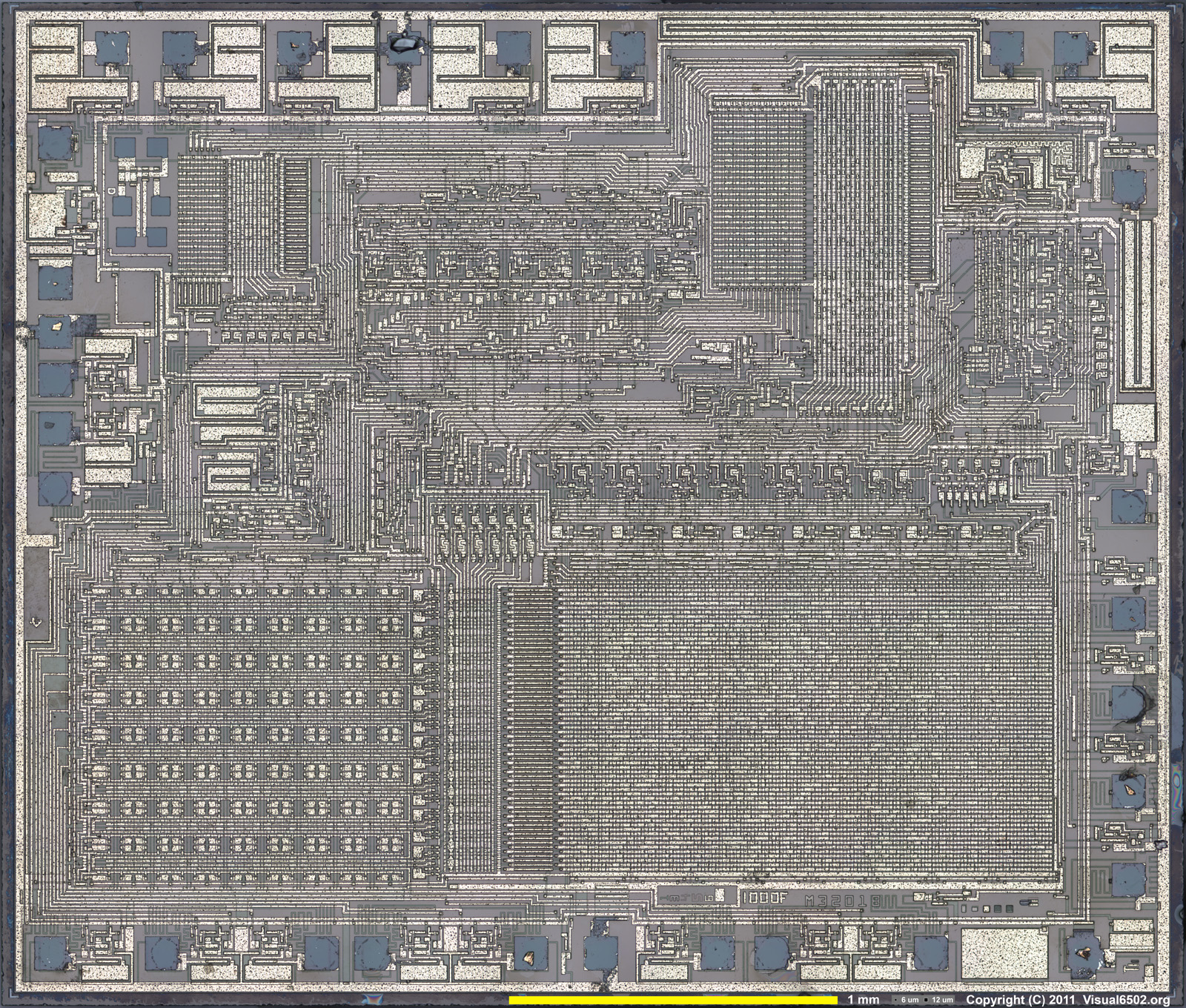
The second is direct examination - taking the top off the chip, scanning it at high resolution and converting that to binary code - the picture is a TMS1100 die.

It would be great if the Microvision stuff was dumped - it's one of the few last old machines that hasn't been dumped yet. Not that anyone would really want to play the games, it's more of a preservation thing.

Reading the MESS source also revealed the clock speeds. I have had a problem with this, because whilst the TMS1000 data book is very informative on coding, it's not on the physical hardware, I couldn't find a clock speed descriptor (the clock circuit values are on Dan Boris' circuit).

In practice, it varies, there are 300Khz, 500Khz and 550Khz clock speeds, which correspond to 50Khz, 83Khz and 92Khz instructions per second (every TMS1x00 instruction takes 6 clocks).

An early example of over clocking. The data book says that fOsc (the clock) has a maximum speed of 350Khz,  on the previous page oddly it says that tc,  the instruction cycle time is 2.5us minimum (e.g. 400Khz).  I guess the Microvision coders had the same problems I did viz. simply getting LCD information to the display quickly enough uses up most of the coding time.

Though in my experiments if you only have 2 or 3 things on the screen, or a few lines, it is quick enough. The diagonal line drawing is slow because it's a pixel plot - effectively PLOT(X,Y) so for X and Y it has to convert it to a bit pattern ($8000 >> x) basically, and that's what takes the time up, not the writing to the LCD. If you have the nibble pattern already, I would reckon BlockBuster works like this for the 'wall' it's much quicker.

Wednesday, 8 January 2014

First Release

So, a first release.

There are two release files, and things are likely to stay this way.

The OSX one contains a Mac OSX executable (mvem) and all the source code. It does not contain the SDL library required to run it,  which can be downloaded from http://www.libsdl.org/download-2.0.php

The Windows one contains a 32 bit Windows executable, the SDL2 DLL, a Code:Blocks project file and a note on how to build it from the OSX source.

Both contain a file test.bin which is the assembled version of the test program. All it does is draw a diagonal line, sound the buzzer continually (the tone varies slightly because the emulator decides the frequency from the total transitions and time per frame, but it will be fine for beeps) and respond to the right column of keys (3 E D C) on the top row.

This is pretty much flogging the hardware to death.

You run it with ./mvem test.bin or mvem test.bin . The debugger commands are : 0-9A-F change code address, K set breakpoint, H home to program counter, S single step, V step over. G run. When running (the debug display will disappear) M returns to debug mode (the other key columns are 1QAZ and 2WSX - a Microvision has a 3 across by 4 down keypad). You can exit either using Escape or the Close button on the window.

It's very primitive, but it works fine.

Minor updates

I've updated three things on the right :

tms1100.def has been updated because of a minor bug

tmsasm.lua has been updated to add in "lcall"  and "lbr" pseudo operations that do a long call and a long branch (on a TMS1100 this takes two instructions, or three if you are changing chapter (don't ask))

test.asm has been replaced completely with the program that draws the diagonal line, responds to the keyboard and tests the beeper, it also has the beginnings of some utility functions.

Interesting comment from Sean Riddle about TMS1100 dumps. Let's hope there are some Microvision ones out there - if so then then after releasing the first version, I will get them working, if not on with the game coding, which will start with extending the utility routines.


Tuesday, 7 January 2014

Aarrrggghhhhh !

What task has taken me the longest in the Challenge so far ?

Is it :

(1) finding the data sheet for the Hughes LCD ?
(2) writing the emulator for the TMS1100 ?
(3) getting the assembler working ?

or is it :

(4) getting code that compiles perfectly under Mac OSX and (probably) Linux, is syntactically correct and uses standard libraries in the proper way to compile in bl**dy Windows.

All answers on a postcard.

I gave up on the command line, I did it in Code:Blocks in the end, following a guide this bloke had written.  Apparently, in s**ding Windows (I'm an MCPD so I'm certified in how bl**dy awful it is) it matters what order you put libraries and command line options. Get it wrong and you get 700 linker errors because it can't find things in a library that you've linked to which is definitely there. Gawd alone knows why.  Why it can't just work like it does on Linux and Mac OSX I do not know.

Anyhow, tomorrow, you will be able to play with the emulator on Windows and MacOSX. It appears to work okay in Windows XP / VirtualBox. The source code will be available for those who think its a virus.

Probably.


Sound and Keyboard now working

I've now got the sound and keyboard working - except for a few tweaks (the emulator still always loads a file called 'test.bin') it is essentially complete.

There will always be a few bugs. I found that (for example) the assembler was compiling TKA as $0B rather than $08 which caused some chaos, as $08 (COMC) is the command to switch to the upper 1k of ROM (sort of).

But hopeful I will release the source later today or early tomorrow - I'll set up XP in a VirtualBox machine and build a DOS version as well, because it's built for a Mac.

Monday, 6 January 2014

Slowwwwwww.......

Another day, another step forward. I've synchronised the Emulator to the timer now, so instead of running at 50Mhz, it's running at 50 kHz.

I must check to see if its over clocked, because they can run up to about 65khz (400Khz clock, 6 cycles per instruction)

Drawing the pixels on the screen above, and doing nothing much else, runs about about 32 Frames a second.

Now, it is fairly slow as a method, because there are loops and lookups in that pixel drawing code, it would be much quicker just outputting four nibbles, but still, it's going to be like programming for the Studio 2 ; do the graphics first and get the frame rate passable, and then fit the game around it.