There's two methods. The TMS1000 patent describes a method of testing the chips by dumping the ROMs serially. It was known this was possible, but not how to do it, but it seems it has been figured out.
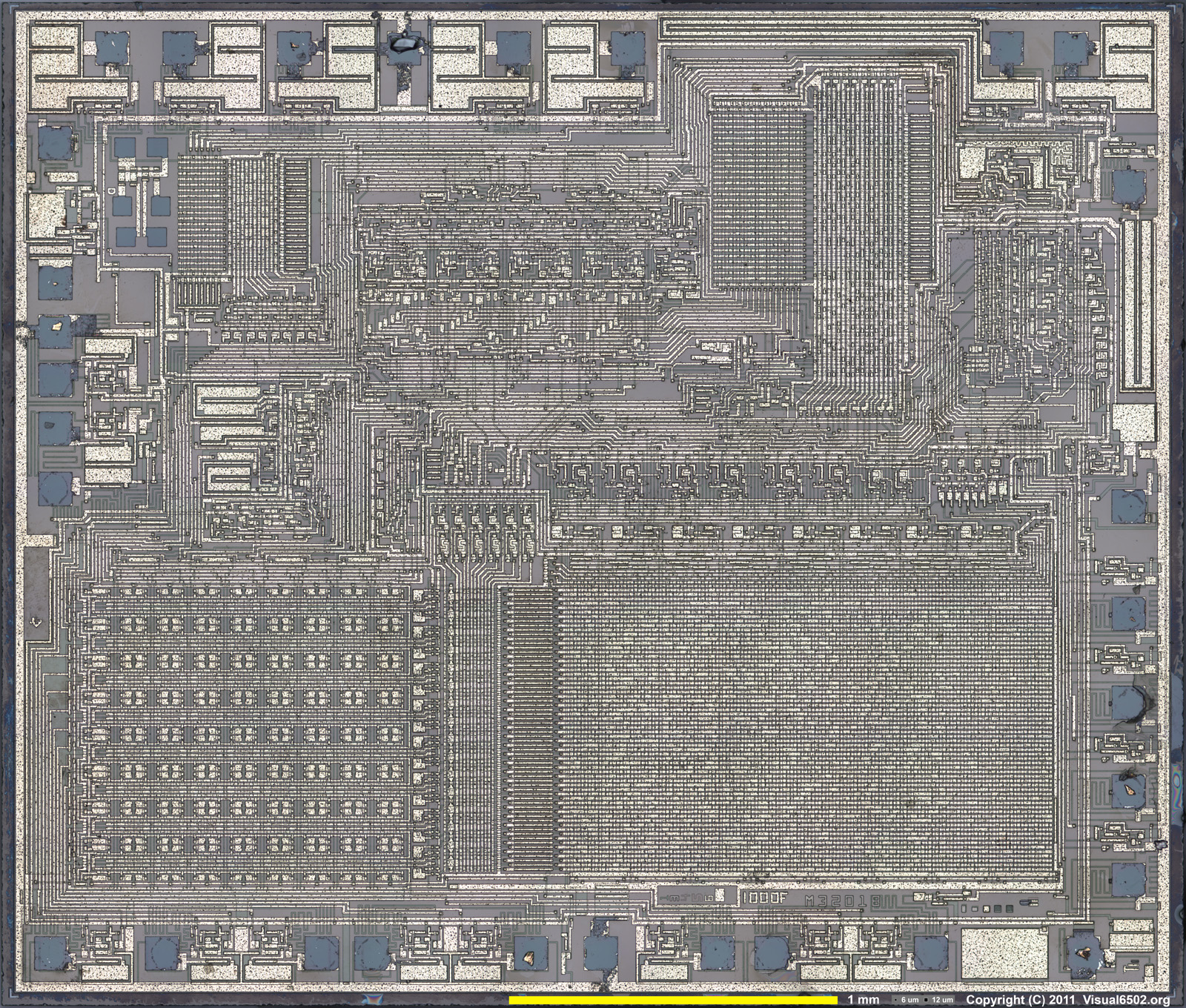
The second is direct examination - taking the top off the chip, scanning it at high resolution and converting that to binary code - the picture is a TMS1100 die.
It would be great if the Microvision stuff was dumped - it's one of the few last old machines that hasn't been dumped yet. Not that anyone would really want to play the games, it's more of a preservation thing.
Reading the MESS source also revealed the clock speeds. I have had a problem with this, because whilst the TMS1000 data book is very informative on coding, it's not on the physical hardware, I couldn't find a clock speed descriptor (the clock circuit values are on Dan Boris' circuit).
In practice, it varies, there are 300Khz, 500Khz and 550Khz clock speeds, which correspond to 50Khz, 83Khz and 92Khz instructions per second (every TMS1x00 instruction takes 6 clocks).
An early example of over clocking. The data book says that fOsc (the clock) has a maximum speed of 350Khz, on the previous page oddly it says that tc, the instruction cycle time is 2.5us minimum (e.g. 400Khz). I guess the Microvision coders had the same problems I did viz. simply getting LCD information to the display quickly enough uses up most of the coding time.
Though in my experiments if you only have 2 or 3 things on the screen, or a few lines, it is quick enough. The diagonal line drawing is slow because it's a pixel plot - effectively PLOT(X,Y) so for X and Y it has to convert it to a bit pattern ($8000 >> x) basically, and that's what takes the time up, not the writing to the LCD. If you have the nibble pattern already, I would reckon BlockBuster works like this for the 'wall' it's much quicker.
I haven't heard back from anyone yet about the ROM dumps, so I decapped Vegas Slots (the only cart I had) and took pics of the ROM array: www.seanriddle.com\vegasslotsrom.jpg The 1 bits are visible, but the color and brightness are exactly the same as the 0 bits, which makes transcribing the 16,384 bits difficult! I'll try to dissolve the top metal layer with acid, and the diffusion below should have much more contrast. There's probably a passivation layer that I'll have to remove with HF; if so, I'll probably have to do that tomorrow afternoon.
ReplyDeleteRanger Lennier of the MESS crew sent me the dumps Kevin made: www.seanriddle.com/microvision.zip
ReplyDeleteLooks like he could dump 4 of the TMS1100 carts, including Vegas Slots. So it will be interesting to see how well I can do visually. On other MCUs, I've got about a 1/2% error rate: www.seanriddle.com/decap.html
Good luck ... way beyond me. I can figure the code out but .... :)
ReplyDeleteCheers - I'll see if I can get them working. Need to write code to map loaded binaries to flat binaries so PC goes 0,1,2 rather than 0,3,7 but this isn't difficult. Might get it running some real code RSN.
I finished visually transcribing the Vegas Slot ROM bits, and the results match Kevtris' ROM dump exactly: www.seanriddle.com/tms1100.html
ReplyDeleteI've dismantled a BlockBuster cart and a Vegas Slots cart and the PCBs are identical (marked 4952 Rev A) - what Revision is your Vegas Slot ROM ?
ReplyDeleteThe same. And it looks just like your pic, except there's a piece of scotch tape running across the board just above the fingers, where the red mask starts. Actually, after trying to peel it off, it's tougher and stickier than scotch tape. On the other side, resistors were added going from one of the jumpers to 2 others, and there's a sticker with 8007MC.
ReplyDeleteI composited the entire Vegas Slots die: www.seanriddle.com/vegasslotsdie2000.jpg
ReplyDeleteIt's probably a good idea to verify the instruction PLA is normal.
BTW- the pic on this page is an unknown TMS1000, so it has 1/2 the RAM and ROM of the TMS1100. The output PLA is not set up for 7-segment output, either. I dumped the ROM bits visually, but the byte histogram doesn't look the same as the TMS1100 games. So the bit layout could be different than a TMS1100, or maybe there's just a lot of data in this ROM that's skewing the histogram. I haven't disassembled it yet to see if it makes sense.