Tuesday 18 March 2014

New Release, (Build 14)


I have upgraded it to Build 14. The changes since the last one are :
  • Added checksums for all known cartridges that are dumped in their current state. If this changes because dump errors turn up, the paddles will work differently.
  • Sea Duel now displays the flag properly (see the 2nd picture from the left - it's meant to be the Stars and Stripes ....). The LCD latency trackers do not change when there are no addressable->output latches in a frame - static displays with only one row/column pair.
  • Sea Duel now plays the tune (albeit it sounds terribly stuttery on Windows XP/Virtualbox, though it seems fine on Mac ?).  Might be a VirtualBox issue.
  • Sea Duel assumed TMS Data Memory was all zeroes on start up, the spec doesn't say this, but it probably is in practice. I suspect this is because they aren't cleared on reset, which isn't quite the same things cleared on power up - you can reset a TMS1100 mid program, but you can't do this with Microvision games.
  • The CPU speed now is correct for some programs (Sea Duel sounded squeaky because its clock is half the speed)
  • The Paddle controls are calibrated for known cartridges, so it is possible to play Baseball which has a way-out range. Other new games (e.g. Connect 4, Super Block Buster) now enable the paddles when loaded.
  • It now starts in run mode. To run in debug mode, prefix the name with an @ (e.g. mvem @sbb.bin)
  • The screen size can be changed by adding wwwxhhh e.g. mvem mind.bin 320x200

Windows and OSX executables are downloadable from the sidebar on the right. The source is in the OSX executable (and is the same for Windows, save for the build process).

Sunday 2 February 2014

Composite Instructions

The various how tos are all over the blog, I thought I would summarise them here.

Stuff is downloaded from the link bar on the right. It all is open source - do what you wish with it, please keep attributions however.

The Emulator

to run the emulator either ./mvem <binary> or mvem <binary>. It requires SDL2 - for Windows the DLL is included, for others you will have to go to www.sdl.org. It doesn't use anything else. The mouse control on Windows does not appear to work properly, and this appears to be a Windows problem. 

The currently available binary images are in both archives. The osx file contains the source files as well (the work was done on a Mac)

If there is an overlay bitmap file - in windows .bmp format, because this is the only format that SDL can read directly.

it boots up in debug mode - the keys are :

0-9A-F  change displayed address
G run program until broken (with M)
K set breakpoint at current address
S single step
V step over
M return to monitor (if running)
Esc exits the debugger

When running, O & P control the paddle,  and 123QWEASDZXC are the Microvision keys. If you write home-brews on it that use the paddle, or have the reversed output as Vegas Slots does, you will have to hard code this in the emulator - each ROM image has a checksum which determines whether it has the paddle hardware or not, what the charging times are (best way to do this is trial and error) and whether the output to the LCD driver is back to front or not. 
 
The Assembler
    
The Assembler is a lua file called tmsasm.lua , which assembles TMS1100 assembler - it is basic but it works. There are plenty of sample codes to see, but the basic differences to some others are :

there are no expressions  - you cannot write tcmiy label+1 for example
ldp, br and call extract the right bit from the address used, you do not have to modulo 64, or divide by 64 modulo 16. 
No support is provided for chapter bits outside comc, obviously. High chapter usage is shown in the space invaders source, which is mostly in the upper chapter.
lbr and lcall are shorthands for ldp x; br x and ldp x;call x respectively.
 
The hardware version

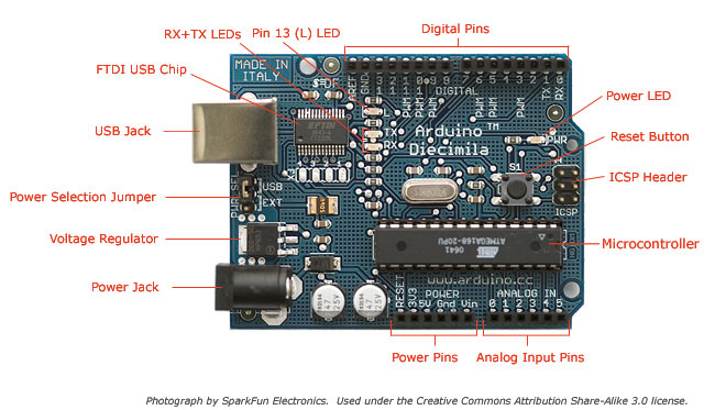
The hardware version requires a directory with the .ino file, the header files copied from the OSX emulator and absolute links to include the C code from the OSX emulator version. Relative links don't work. You can see this in the .ino file. It is designed for a 328 based Arduino (e.g. Duenamolive in this case) but it should work okay on most Arduinos or other MCUs really , all it does is scan the various hardware bits. The .ino code just translates hardware calls into Arduino compatible ones. 

The wiring is very basic. It uses a LCD4884 shield, available from most of the usual suspects. The buzzer is connected to Pin 8 via a 100R resistor , and the keypad as follows:

Arduino 13 -> Keyboard 3 (C0)
Arduino 12 -> Keyboard 1 (C1)
Arduino 11 -> Keyboard 5 (C2)
Arduino A5 -> Keyboard 2 (R0)
Arduino A4 -> Keyboard 7 (R1)
Arduino A3 -> Keyboard 6 (R2)
Arduino A2 -> Keyboard 4 (R3)

The keypad is one of those stock 3 x 4 keypads available cheaply from most suppliers with rows : 123 456 789 *0#


Saturday 1 February 2014

Next up .... this

In the ever moving down the game system coding ladder, this is my next target.

It's called the 'Entex Select-A-Game'. This one is colour, sort of, on a 16 x 7 Grid - so it is half the resolution of the Microvision.

Wednesday 29 January 2014

Round Up

Overall, I'm quite pleased with this RetroChallenge, after the mess of the last one anyway, which never really got restarted when I went on holiday.

I achieved most of what I planned - emulator, new game (actually two) and an Arduino version.

The 8021 was about 3/4 completed, but I never really went anywhere with it. It's more challenging to write for a TMS1100, and it's supposed to be a challenge.

It went a bit sideways in the middle, when the ROMs turned up. People have been thinking about home-brew Microvision games and emulators for years, but nobody dumped the ROMs even though it was known to be possible, and then two came along at once.

Thanks especially go to : Sean Riddle, Kevin Horton and Dan Boris.


Final Code Release

Must be a boring film....
So, another Retrochallenge month comes to an end.

I've updated everything and rebuilt everything. The emulator has changed slightly, not bug fixes but changes to work with the Microvision / Arduino in the source, mainly to do with types (I forgot Arduino ints are 16 bits, longs 32 etc.). The main problem was that the rotary control only worked about 2/3 off the screen (due to wrap-around in the integer).

One mistake was that I put the rotary control checking stuff in the SDL hardware driver, so that came out and went where it belonged in the shared code.

Microvision.ino is a new upload. This is the Arduino file and is the extra bit you need besides the original source. Arduino doesn't really like complex project structures (not that this is complex) so you have to copy the header files from the source in and include the two shared files as a direct address link (e.g. the full path). It doesn't seem to work otherwise.

The last upload is a big one, 66Mb in size, it is the complete project tree off my machine, which contains everything.

I really must learn to use github and so on for the next project.


Sunday 26 January 2014

Saturday 25 January 2014

Hardware Version, progress report #4

10k Pot added to the breadboard
Well, I think I've pretty much finished.

I found a 10k Pot in my box, from memory it was one of a batch I bought to repair a Microvision unit where the rotary controller was broken, and wired it into the remaining analogue port, and it plays fine.

Sound and Graphics work okay. There are a few minor graphic problems which relate to the incomplete emulation of the LCD.

Tomorrow I'll try the full LCD latency emulation and see how it works, it might well still be quick enough.

I will pinch our camera and make a video of some sort of the game being played, so you can see it is for real :)

One thing I forgot is that gcc-avr and gcc-x86 have different ideas about how big ints, longs and so on are - this was causing an overflow on the potentiometer calculations on the AVR, but it now all seems fixed and running nicely.


Hardware Version, progress report #3

After a lot of cursing regarding the Keypad library - the people who wrote it, it didn't seem to occur to them to have a simple 'is a key down' test, which is pretty helpful if you are programming games, I've got the keypad working.  I might just chuck the keypad library and access the controls directly, rather like the LCD4884 library it is a bit limited.

I've also added the sound, which worked very well. The thing now beeps at me if I leave it alone though, Microvision carts do this to warn against battery usage.

So in BlockBuster you can now set the parameters and start the game up, of course you can't play it because I have done the pot (yet).

I always found Block Buster really difficult anyway, even on a real Microvision.

Hardware Version, progress report #2

Dracula has risen from the grave
More progress this morning. As you can see from the photo on the right, the Emulator now seems to be working okay under the Arduino. The beeper and keyboard don't work yet. I will try and getter picture later on, but it does display "7 ST" which is the opening screen of Block Buster.

If I'm going to test it with Block Buster I'm going to have to add the potentiometer to the circuit, I think I have a few in the spares box somewhere.

It took longer than I though, because when I actually came to look at the LCD4884 library it is pretty useless except for drawing text (actually it doesn't do anything else at all !), so I had to grab the driver data sheet and poke the controller directly. This ended up being beneficial as the "dirty screen code" ended up being optimised for the way the controller worked, not the way the library worked.

Strange fact of the day : My watch was an hour fast for most of yesterday and I didn't notice......

Friday 24 January 2014

Hardware Version, progress report #1

Arduino board
Some progress on the hardware. The code is built and running on the Arduino, and it appears to be working. I've not written any of the actual rendering code, but dumping what the LCD should be to the serial port shows that the rendering data is correct.

So if I actually dump that status to the LCD, then I should be getting (hopefully) the start up screen on the display.

The Arduino thing is a bit annoying. The 'IDE' is nice and easy if you just want a few simple bits, but try anything complicated and it just falls apart. The only way I can figure out to cross compile without abandoning it altogether is to #include the C files with a full path name (presumably because it copies source somewhere else - gawd knows). If you put the C files in the directory it compiles them, but bizarrely doesn't link them in.  The Arduino is a great bit of hardware, and so is avr-gcc and avrdude, but the Arduino toolkit outside that is messy.

(One of the things I hate about the Mac is that there isn't a bl**dy key with a hash on it on the standard keyboard. So typing in #include or whatever means you have to press ALT 3. It's really annoying. The big keyboard has one but isn't wireless......)

The implementation is going to be pretty basic. I hacked the emulator so it dumped an include file line creating the ROM image in Arduino ROM if you precede the file name with an 'at'. That then is included into the source code which is compiled and uploaded.


Hardware Prototype

Microvision 2014
I now have a working hardware prototype. It is an Arduino Duemanolive (or however you spell it....), a Piezo Beeper, a 100R resistor for the Beeper, the LCD48x84 Shield and one of those cheap 3x4 keypads.

The shield plugs on the top, the beeper is connected to Pin 8, and the keyboard is connected as follows:

Arduino 13 -> Keyboard 3 (C0)
Arduino 12 -> Keyboard 1 (C1)
Arduino 11 -> Keyboard 5 (C2)
Arduino A5 -> Keyboard 2 (R0)
Arduino A4 -> Keyboard 7 (R1)
Arduino A3 -> Keyboard 6 (R2)
Arduino A2 -> Keyboard 4 (R3)

Leaving A1 free if I ever decide to implement the rotary control (which would just be a pot on there !). I make use of three libraries, Beep (included as standard) LCD4884 (v1.2) and Keypad


Release 11

A new release of the Emulator, for Windows and OSX and Linux probably. Source is in the OSX bundle.

What's new :-

  • Support for Pinball Game
  • Support for Overlays (included for Pinball)
  • Paddle controllable by Mouse
  • Game main display enlarged

For some reason the paddle control by mouse does not work under Windows. I don't know if this is SDL, VirtualBox (I build under XP/VirtualBox) or me - it seems to work perfectly under OSX and the code is very simple, a call to SDL to tell it to pass events on and a bit of code to change the rotary control in response to those events.

I will have a look later on.

Overlays have to be in .bmp format (same name as cartridge) unfortunately as it's the only format that SDL will load without support libraries.

Overlays and Mouse control added.

Made some changes this morning - the main ones  you can see here. When running the display now takes over about a quarter of the screen rather than just being up in the corner (still there for debug mode) & I got rid of the grid (useful for debugging but not otherwise), and the overlay is over the display.

The mouse also controls the paddle - you can still use O & P but this is much better.

I have one fix to make later - the pinball rotary timing is different for the Pinball cartridge, this manifests itself as not being able to go to the right hand last quarter, which makes playing the game difficult.

For some reason, probably the scanning of the overlay being a cm or two off the scanner surface or possibly the blurring or both, the circles aren't in quite the right position, but then this was only a quick hack up of the overlay anyway. My coding skills aren't bad, but I cannot draw at all. I think this is why I quite like coding games for these sorts of machines ; put me on a PC or Tablet and the graphics talent shines through, sort of ...

I will update everything when I've fixed the Pinball timing, which will be later today sometime hopefully.

Couple of ideas

Knockup Pinball Overlay
Couple of ideas appeared in the comments today. A great idea to use the mouse for the paddle controller, and Pinball. Pinball really needs the overlay to be playable, so I ran a cartridge through my scanner (so I can get the scale right !) and painted in the areas to get a very rough and ready copy of the pinball overlay as a PNG.

So today or this weekend I'll get that up and running and make the mouse control work.

Thursday 23 January 2014

Everything now current again.

So, everything has been updated on the right apart from the old data sheets - everything is, I think current.

The main changes is that the Emulator now has a proper latency implementation. The picture on the right (Bowling again) shows the two pixels rather than one, and it doesn't flicker like the optimised one does.

The Space Invaders source has been packaged with a Binary and updated (it does run on MESS) and so has the system library, though I don't think that's been updated since the last time I used it.

Windows, OSX and source versions are available. Linux users should fine it compiles fine from the OSX sources. Windows users who want to compile it, well, good luck !

Space Invaders uses three keys, one from the left row, one from the middle, and one from the right. You move with left and middle, and fire with right.

To get off the static score screen press Left/Right (e.g. Left and Middle on the keyboard) at the same time.

It doesn't matter which row you use .... I've got 1k of code to fix the key routines if anyone really minds.

Too smart for my own good.

This is the Microvision Bowling Cart which was dumped in the last day or two by Sean R.  by the carve the top off and take a picture with an electronic microscope method.

Unfortunately it didn't work properly on the emulator. A couple of easy fixes - it has the 'reversed output' like Vegas Slots,  and there were a couple of error bits that meant it went haywire.

But it kept flickering - switching 45 degrees all the time. I thought it was a timing bug or possibly a polarity reversal issue. MESS was fine (albeit the data was bit reversed) and MESS doesn't do the polarity reversal, not that it actually matters, you can't have too much DC in an emulator.

It was actually my try-to-be-too-smart optimised LCD code, which tried to second guess the programmer as to whether they were writing vertically or horizontally or both to the LCD controller. It got it right, but this cartridge, technically does both, sort of. The top left most pixel should be set as well as the one below it, but because it does multiple writes to these lines, it got confused, and switched between the two all the time. So sorry, that was really dumb and I hope I haven't wasted too much of Sean's time.

So my plan X is to write a proper LCD rendering routine and use that for the PC based emulator and the row one for the Arduino (I don't think it could do a pixel based one and keep up). This isn't hard, my optimised version treats a row as a single entity with a single entity whereas in reality each pixel has its own latency. This will mean the bomber game which draws everything as columns won't work on the Arduino.

Once I've done that I will update everything, rebuild the Windows version and so on.

Then maybe this weekend I can see if I can build the hardware version.


Wednesday 22 January 2014

Space Invaders ... completed.

The game is basically finished, coming in at exactly 1,000 bytes, slightly less than half the ROM space of the TMS1100.......

I'll update all the code and stuff after I've tested it a bit more, but it seems to basically work fine.

Space Invaders Session 4

It's now basically playable. The screen shows a game in progress.

You can shoot the invaders - they shoot back.

There's no end of level, or invaders landing test yet, and if you are hit the game just freezes.

But that's for another session, tidying up, displaying the score and lives, and so on.

Current code size is about 900 bytes of a 2k ROM, and just over 1000 lines of TMS1x00 assembler in four files. The current version (zipped) is downloadable from the links on the right, obviously it isn't finished yet.

I haven't tried it on the MESS emulator yet, I did try Bomber and that works fine. It should actually work better because MESS emulates the pixel latency properly, mine's a short cut.

In other, err.... news, Sean has decapped a BlockBuster and examined the PLA, confirming visually what we thought was the case anyway, that the PLA inverts the output on Vegas Slots (or to be more precise, every other game so far inverts the outputs !)

Space Invaders, session 3

Not Microvision Graphics btw.
I can now shoot the invaders, and keep score. Now need to get them shooting back - and tidy up - check for level over, landing, shot etc.


Tuesday 21 January 2014

Space Invaders, Session 2

Little progress today - the base at the bottom can move and you can 'fire' a missile, though it doesn't actually go anywhere yet :)

Should do a bit more tomorrow.

L8R: Got it moving up the screen, and detecting the rows, now need to match the position to the row bits.

Monday 20 January 2014

Space Invaders, Session 1

A start made on Space Invaders. The basic rendering is done and working, and you can't see it here, but the 'march down the screen' bit also works - if you run the app it starts up the top right, goes to the left, down one, goes to the right and so on.

This is the first time I've written cross-chapter code. A TMS1100 is a TMS1000 with the extra 1k ROM bodged on using a Chapter Buffer, Chapter Address and Chapter Subroutine Store, which means that the actual program counter (423) is built up of three numbers - Chapter Address (one bit), Page Address (4 bits) and Program Counter (6 bits), making 2k in total.

I thought this would be annoying to program, but actually it doesn't make much difference. You can't actually set the CB flag (that is copied to CA when you jump/call) , just toggle it, so that's one thing to keep track of but it isn't that much of a problem to do so.

 Note there is very little animation in this game, just moving blocks. But that applies to virtually all Microvision games.

Sunday 19 January 2014

The next game will be ... Space Invaders

Okay, so it's not horribly original. But it's a reasonable second game after the trial bomber game. This shows a mock up.

I decided against shields, because it would reduce the invaders space (err...) - there probably won't be any saucer across the top either.

There's a limit to what you can draw in a 16x16 grid !

I've also updated the bomber.asm and tms1100 assembler, so it can use include files - I did it just by concatenating the files together before but that meant the line numbers on the error messages were wrong.

A Thirty Year Event !

Yes, for the first time in thirty years (possibly because no-one else has been daft enough to do it) there's a new game for the Microvision.

It's one of those left to right Bombing the city flat games, where you have to clear a landing strip.

There are two keys - anything in the middle row drops a bomb, and anything on the left continues the game (when a level is over, because you've crashed or landed, it displays your score).

Source code has been added to the link list on the right. The assembler has also been updated (minor tweaks), the system library (ditto), and the Windows and OSX versions of the emulator (which contain the binary files).

Windows still has this clearing-one-byte behaviour (on resetting the TMS1100 it writes zero into code Memory [0]) that goes away with the insertion of an effectively null code line. I read through the code, and put a fair few ASSERTS in - I wondered if a rogue value got into X or Y and that caused a memory write , C not being protected, but can't see any problem. It's possible it might be in SDL of course.

Saturday 18 January 2014

Bomber, part the third

Bomber is now working, pretty much. The game core bit is playable, it has sound effects (well, in as much as a Microvision can manage them), the only bits left to do are the start a new level bit, and the end of game score display bit.

It does require a new version of the emulator (to fix the issue with row/column based rendering on the LCD, or to be precise my shortcut implementation of it !) so I'll probably release the updated executables, source and so on later this week. The assembler has been tweaked a bit as well.

The screen grabs look much the same, so here's a picture of an Avro Lancaster. If you're interested in this plane, Leo McKinstry's book is an excellent history of its design, production and use (he wrote similar books about the Spitfire and Hurricane)


Friday 17 January 2014

Bomber, part the second

Bomber running in the Emulator
Only a little progress today for various reasons. Hope to finish it tomorrow, will be a quiet day tomorrow.

Minor improvements made, both to the 'skyline' and the bomber and bombs are both visible on the screen - the bomber in the top left and the bomb about 1/3 of the way down.

Coding for Microvision is a bit like a 2600 in some ways - the screen display is pretty much everything and the rest wraps round it.

This is going to be a fairly primitive game - aren't they all :) - just bombing with increasing speeds and displaying a score at the end of the game.

Then I'll think of a second game to do that will be the main game for the Challenge.

Thursday 16 January 2014

Bomber , part the first.

First bit of working bomber code, showing the 'buildings' (okay single square pixels) that  you have to flatten with your bomber and bomb (both single square pixels).

Not much for the Graphics Artists here.

Showed up one bug though. The LCD rendering/latency code is optimised for column data writes (e.g. writing a line horizontally) - this renders lines vertically (so it can keep the building heights as a table - see bank 1, the numbers correspond to the building heights), but of course that doesn't work properly.

I don't want to do it a la MESS where it tracks each pixel individually, so I'll have to have a row based renderer and a column based renderer and switch between the two depending on the data in the latch. Which will be basically the same thing, might blink at switch over.

It's not a cycles issue for a PC or a Mac, but I still hope to get an Arduino version working, and that might be short of CPU cycles. No big problem really :)

Fix for tomorrow I think.

Minor Updates

Couple of fixes to the assembler - it didn't handle page overflows properly following the conversion to the LFSR program counter, and labels can now have underscores in them.

I have also uploaded the current version of the system routines on the links page as well.

Further to the weird Windows only bug, I'm going to code read the emulator source in case I've done something daft, wouldn't be the first time :)

Okay, so I decided to do something a bit different

This is a mock up of the first new Microvision game in 30 years ...

It won't ever be done on a real Microvision, though - probably.

Not because it's technically impossible, actually it's technically not that difficult, but because the Microvision main units are so fragile that it's a rather expensive experiment.

This is a Cheetah3D model.

(Note that I'm not quite sure how you do the insert round curve at the top yet ....)

Library routines move onward

The support library is coming along quite well, I'm quite pleased with it. It currently occupies only four pages of ROM memory, and wastes only about 6 bytes - this is because a TMS1100 divides memory into pages of 64 bytes and you can't cross to a different page without a jump, it's not like a Z80 where memory is contiguous.

The screenshot uses about 12 bytes to - clear the screen, play a beep, display a number and increment it (the latter is for keeping scores and so on) - you can actually see most of the code in the screen shot. It operates like a fast counter. I suspect on a real Microvision it would be extremely blurry in the least significant digit because the LCD isn't one of the greatest available.

Functionality at present is :

  • Microvision hardware initialisation
  • Writing a row or column bit pattern to the LCD latches given a row or column number
  • Performing a Display Update
  • Performing Display Polarisation switching
  • A sound system that runs in the background (sort of - it toggles the speaker on the update and does the timing on the polarisation) which allows beeps of about 0.5 seconds or so and half a dozen different beeps, all dependent on how frequently you update the screen :)
  • 3 x 5 digit font for scores / settings and the code to select it.
  • Render a four digit number to the screen at any vertical position, optionally updating font data
  • Clear screen routine / Zero score routine
  • 4 bit Random Number Generator - bit rubbish but useable.
  • Add 1, 10 or 100 to the 4 digit number (for scoring, mostly)
There's no keyboard routines or other utility functions - not sure what to provide, rotate functions maybe ?

Wednesday 15 January 2014

Completing the Number Rendering Functions

Only spent a little time on it today, but got the number rendering thing working reliably - the picture shows it in action.

You can see from the debugger that banks 4,5,6,7 hold the information on each digit - the first number is the actual number, the next 5 the pixel equivalent.

In other, err.... news, I've been dismantling Microvision cartridges (real ones) to see if I can help the MESS dumpers - bit beyond my electronics skills for me - with only limited success.

Looks like a fair few are going to have to be dumped the hard way - carving the top off, using some sort of high power scanner on the chip, and translating that into binary data.

Fun ..... not. But it is worth preserving these things where possible.


Tuesday 14 January 2014

Creating some library functions

I always use reusable code where possible , and even a TMS1100 is no exception. I've written a slightly demented bit of code this evening which takes a digit (0-9) and stores a pixel version of it in memory.

Not difficult in most processors, but in an TMS1100 it has to fit in 64 bytes otherwise its pretty useless as a subroutine (branching to another page is possible - you can go the the opposite chapter, I think, but not a different page in the same chapter, because PB is used for the subroutine return address and the page register.

Just need to write some code to physically render it to the LCD.

Not sure what sort of game to write yet. A version of the old Bombing game where you go left to right across the screen trying to flatten buildings, maybe, as a first run. Or maybe something else.

Coding in these things often uses a FSM type approach, rather than a modular approach. It's difficult to be modular when you only have one level of subroutine, and fairly small subroutines.

New Working Versions and Source available

Windows and OSX versions are now available for download. The OSX tar ball contains the source, the Windows just the executable.

You run it with ./mvem test.bin or mvem test.bin . The debugger commands are : 0-9A-F change code address, K set breakpoint, H home to program counter, S single step, V step over. G runs the loaded program - it starts up in debug mode. When running (the debug display will disappear) M returns to debug mode (the other key columns are 1QAZ and 2WSX - a Microvision has a 3 across by 4 down keypad). The P and O keys turn the paddle (position shown by a bar below the main display). 

You can exit either using Escape or the Close button on the window.

There's one oddity. The OSX one worked fine, but when I ran the Windows version it didn't work. It was inserting a 00 value into the first byte of the array used to store the code. This has been fixed, sort of, by inserting a bit of code which effectively does nothing in the reset() code. I am wondering if this is an optimisation bug .... or another bug in my code. But it works, anyway.

Also included are the four ROM images - Vegas Slots, Phaser Strike, Block Buster and Mind Buster. Blockbuster is almost unplayable but then it always was .......

The other things - the assembler, definition file and parser have been updated as well.

Not perfect, but not bad. Next part of the Retrochallenge is to write a new game for the system.


Monday 13 January 2014

In which I admit idiocy.....

So, I've fixed the bug. Apart from the LCD Reversal in Vegas Slots, all is now hunky dory.  (though I still haven't implemented the rotary control yet).

All that time spent double checking the TMS1100 code, it wasn't that. The problem was not that some of the games had backward controls, they all did, and I hadn't noticed. So that's my own stupid fault really.

The reason was simple enough ; Dan's schematics are either wrong or from the back perspective .... so all the wiring is back to front and upside down, so when I used those connections (it is correct in the MV technical document) unsurprisingly everything came out the wrong way round......... the CPU core always worked fine.

So, anyway, after all that idiocy I will implement the rotary control - Block Buster works fine but you can't actually play it and you can't remove the control.

A consequence of this is, I think , the O-PLA is doing the job of reversing the output on cartridges other than Vegas Slots.

This is kind of understandable. The LCD Datasheet does use "Data 0" "Data 1" "Data 2" and "Data 3" for its connectors, but they are the 'wrong way round' from normal, e.g. I think Data 0 is actually the most significant bit. I wonder if somewhere in the early development of these games - which would have been on a separate machine without real test hardware I guess - someone made that mistake.


On the trail of the Lonesome Bug

Block Buster PCB (Track side)
Well, a few steps forward, a few steps backward.

I've dismantled a BlockBuster and Vegas Slots cartridges and they are identical. So it's not a wiring issue.

I've also run the MESS Microvision Emulator. (MESS is a program which emulates virtually every computer and console ever made ....)

This , interestingly, has exactly the same problem with 'Vegas Slots' that I do, viz. the display is backwards - it behaves as if every nibble written to the LCD is backwards, other than that it works fine.

So it may not be just me, it might be the PLA for the O-Lines.

The MESS author derived his technical information from a different source from me, and implements his processor emulation differently, so it is odd that we have the exact same 'bug'. If it is a bug.

However, it does have the keyboard the right way up on Phaser Strike, which suggests that its an error on my part, which I will have to track down.

MESS works well, except for it tries to fit the 16x16 screen to the whole display, which makes the pixels very very big indeed.

Sunday 12 January 2014

A fairly quiet day

Not done a lot today - tweaked the assembler so the changes I made yesterday are the same - I've also made the assembler generate code in TMS1x00 PC order, rather than normal counter order so I don't have to maintain two lots of code, but it's still flattened in the emulator so it looks normal.

Thanks to Sean's scan of the output PLA I know that the mapping of O register -> O lines is 1:1 on Vegas Slots, need to check the physical wiring tomorrow - I do have a couple of Microvisions and most of the cartridges made.

Oddly MB seem to have made different cartridge designs rather than just two - a TMS1100 and an Intel8021 one.

Saturday 11 January 2014

In which I make a stupid mistake.

Vegas Slots running
I've solved the puzzle of the difference between the manual and the code, and a couple of things that nearly but didn't quite work.

I noticed when running BlockBuster there appeared to be a second ball image running in parallel with the first one. I wondered if this was a feature of the rendering rather than the actual code, but it appears not.  So I did a review of the TMS1100 Code.

There's two dumb errors there. On TMS1100 with operands, some operands are reversed. So YNEC 4 is actually

0101 0010

where 0010 is the operand, backwards (e.g. 0100, 4 in binary). What I've only just noticed is that the bit test operands (RBIT, SBIT and TBIT1) and the Load X immediate LDX also have backwards 3 bit and 2 bit operands respectively. The only ones that aren't reversed at Branch and Call, with their 6 bit operands.

This explains much. I thought it strange that LDX 4 was used when according to the documentation it shouldn't work. But it was right, because LDX 4 was actually LDX 1 (e.g. it is 00101 100 - I interpreted 100 as 4 but it's actually 001 , e.g. 1) - so X was in the range 0-3, so the book is right (and the Microvision emulation in MESS is wrong).  Apart from this it didn't matter, it just put the rows in the wrong order because LDX is the only way you can load the X register, you can't increment it, decrement it, load it from memory or accumulator, all you can do is put a constant in it.

The bits were worse, it's remarkable anything worked at all. These are also reversed, so I was interpreting SBIT 1 (which is 001100 10) as SBIT 2 (e.g. the 10 should have been reversed), hence it set the wrong bit.

This was the cause of the spurious ball in Block Buster and also the weird cocked up display in MindBuster, which now looks right.

Of course there are still problems. Phaser Strike works perfectly except that the keypad is upside down - the setup keys are at the bottom rather than the top. It's possible that this might be because in Phaser Strike the cartridges are wired differently. Vegas Slots too works perfectly except it has the same problem that Block Buster did originally, viz. all the graphics or back to front and upside down. This might be simply because the 32 x 8 bit O mask ROM is wired differently. Or it might be another bug. I will have to investigate more closely.

Anyhow, I'm going to try to emulate the rotary control, then I will release another emulator so you can have a go at playing the Microvision games for real.

Friday 10 January 2014

Sometimes real code works .......

BlockBuster working
So, following the last post, I decided to see if it worked.

I removed the test mentioned in the TMS1100 data sheet - only updating the R-Latches if the X Index register was less than four.

It partly worked - except it came out back to front and upside down. Turns out that the LCD input was reversed, which I fixed by reversing the bits on the LCD driver (equivalent to reprogramming the Parallel Output ROM to do it), and as you can see it works well enough.

Hitting a few keys at random it appears to do what the BlockBuster Cartridge does (haven't checked this properly yet), and it also starts up the game and displays the initial wall.

I wasn't, originally, going to emulate the Rotary Hardware, but perhaps I will now, just to see how it works.


Running real code is usually asking for trouble.

Self Portrait
Thanks to Sean, Kevin and the MESS team I've got some real code running. It's quite interesting.

One of the big issues with the TMS1000 is the instruction set is mask programmable. It's not like a 6502 when you know what you are getting or like a Pentium when you know 2 + 2 = 7, you can (I think !) order it with a reorganised instruction set. I kind of reckoned nobody ever bothered, I mean if you did that the development tools wouldn't work.

I've been running BlockBuster on the emulator (It's one of those knock the bricks out of the wall games) . One of the first things it does is display something like 7 ST (a bit like this http://home.comcast.net/~eichler2/microvision/MicroBlockSim.htm).

It sort of works. It displays something, but not what it should.

Looking at the code, I find this (note for people even more pedantic than me - code has been remapped from the LFSR PC to a standard counter PC. If you don't comprehend this this means you are a normal human being).

796   ldx 4          // set X index to 4
797   tma            // Load Memory(4,Y) to accumulator
798   tdo            // put A (pixel data) on output lines to LCD
799   tya            // save Y in A (this is the ptr to the data)
79A   tcy 7          // set Y to 7 (the data clock latch)
79B   rstr           // set data clock (latch 7) to 0
7BC   setr           // set data clock (latch 7) to 1
7BD   tay            // restore the pointer.

which is all very sensible. This should load a nibble into the accumulator (Y points to the pixel data at the start), put it on the LCD data bus and put a pulse on the data clock line to load it into the latches, it preserves the pixel data pointer whilst it does this).

However ....... it doesn't work.  Single stepping this code, it doesn't output the data to the LCD.

Because ... it shouldn't work

The reason it shouldn't work is in the TMS1x00 Programmer Guide.

It says (page 8-12) "The operation of the SETR and RSTR commands is possible for 0<=Y<=15 and 0<=X<=3. And it explicitly says - the X register must be <= 3.

(I note that the Microvision emulation for the TMS1x00 doesn't test this. This might be because they know more than I do, or because they are working from the TMS1000 which doesn't do this test, because X is always 0,1,2 or 3)

A brief perusal of the code above shows X isn't in the range 0-3. It's 4. So , according to the book - it shouldn't work.

Now the code is obviously - to me anyway - doing what it should. It makes logical sense, and it may well work without this test.

Whether the book is wrong (other lists don't mention this X requirement and it does seem a bit pointless !), or the chip is a special one, I don't know. The problem is, of course, if the chip is a special this is an entirely new issue. It doesn't seem to be, what I see of this code makes sense. So I'm going to fix it so it works irrespective of X is and see what happens.

From the challenge view point it doesn't matter as I'm writing a new game not an old one, but if I can get it working reasonably I know my emulation is okay. (If you do nothing it beeps three times to warn you which kinda makes sense). I do have a Microvision so I must see if it actually does this.

The display, we shall see.


Thursday 9 January 2014

Other MB work

I'm still looking for the Microvision ROMs - hopefully I can get some of the early dumps that some of our technical geniuses have done.  Apparently the MESS Microvision emulation does work - to some extent anyway, and browsing that source my interpretation of the controller and theirs aren't that different.

There's two methods. The TMS1000 patent describes a method of testing the chips by dumping the ROMs serially. It was known this was possible, but not how to do it, but it seems it has been figured out.

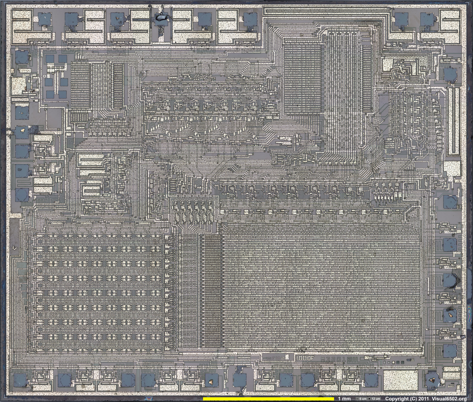
The second is direct examination - taking the top off the chip, scanning it at high resolution and converting that to binary code - the picture is a TMS1100 die.

It would be great if the Microvision stuff was dumped - it's one of the few last old machines that hasn't been dumped yet. Not that anyone would really want to play the games, it's more of a preservation thing.

Reading the MESS source also revealed the clock speeds. I have had a problem with this, because whilst the TMS1000 data book is very informative on coding, it's not on the physical hardware, I couldn't find a clock speed descriptor (the clock circuit values are on Dan Boris' circuit).

In practice, it varies, there are 300Khz, 500Khz and 550Khz clock speeds, which correspond to 50Khz, 83Khz and 92Khz instructions per second (every TMS1x00 instruction takes 6 clocks).

An early example of over clocking. The data book says that fOsc (the clock) has a maximum speed of 350Khz,  on the previous page oddly it says that tc,  the instruction cycle time is 2.5us minimum (e.g. 400Khz).  I guess the Microvision coders had the same problems I did viz. simply getting LCD information to the display quickly enough uses up most of the coding time.

Though in my experiments if you only have 2 or 3 things on the screen, or a few lines, it is quick enough. The diagonal line drawing is slow because it's a pixel plot - effectively PLOT(X,Y) so for X and Y it has to convert it to a bit pattern ($8000 >> x) basically, and that's what takes the time up, not the writing to the LCD. If you have the nibble pattern already, I would reckon BlockBuster works like this for the 'wall' it's much quicker.

Wednesday 8 January 2014

First Release

So, a first release.

There are two release files, and things are likely to stay this way.

The OSX one contains a Mac OSX executable (mvem) and all the source code. It does not contain the SDL library required to run it,  which can be downloaded from http://www.libsdl.org/download-2.0.php

The Windows one contains a 32 bit Windows executable, the SDL2 DLL, a Code:Blocks project file and a note on how to build it from the OSX source.

Both contain a file test.bin which is the assembled version of the test program. All it does is draw a diagonal line, sound the buzzer continually (the tone varies slightly because the emulator decides the frequency from the total transitions and time per frame, but it will be fine for beeps) and respond to the right column of keys (3 E D C) on the top row.

This is pretty much flogging the hardware to death.

You run it with ./mvem test.bin or mvem test.bin . The debugger commands are : 0-9A-F change code address, K set breakpoint, H home to program counter, S single step, V step over. G run. When running (the debug display will disappear) M returns to debug mode (the other key columns are 1QAZ and 2WSX - a Microvision has a 3 across by 4 down keypad). You can exit either using Escape or the Close button on the window.

It's very primitive, but it works fine.

Minor updates

I've updated three things on the right :

tms1100.def has been updated because of a minor bug

tmsasm.lua has been updated to add in "lcall"  and "lbr" pseudo operations that do a long call and a long branch (on a TMS1100 this takes two instructions, or three if you are changing chapter (don't ask))

test.asm has been replaced completely with the program that draws the diagonal line, responds to the keyboard and tests the beeper, it also has the beginnings of some utility functions.

Interesting comment from Sean Riddle about TMS1100 dumps. Let's hope there are some Microvision ones out there - if so then then after releasing the first version, I will get them working, if not on with the game coding, which will start with extending the utility routines.


Tuesday 7 January 2014

Aarrrggghhhhh !

What task has taken me the longest in the Challenge so far ?

Is it :

(1) finding the data sheet for the Hughes LCD ?
(2) writing the emulator for the TMS1100 ?
(3) getting the assembler working ?

or is it :

(4) getting code that compiles perfectly under Mac OSX and (probably) Linux, is syntactically correct and uses standard libraries in the proper way to compile in bl**dy Windows.

All answers on a postcard.

I gave up on the command line, I did it in Code:Blocks in the end, following a guide this bloke had written.  Apparently, in s**ding Windows (I'm an MCPD so I'm certified in how bl**dy awful it is) it matters what order you put libraries and command line options. Get it wrong and you get 700 linker errors because it can't find things in a library that you've linked to which is definitely there. Gawd alone knows why.  Why it can't just work like it does on Linux and Mac OSX I do not know.

Anyhow, tomorrow, you will be able to play with the emulator on Windows and MacOSX. It appears to work okay in Windows XP / VirtualBox. The source code will be available for those who think its a virus.

Probably.


Sound and Keyboard now working

I've now got the sound and keyboard working - except for a few tweaks (the emulator still always loads a file called 'test.bin') it is essentially complete.

There will always be a few bugs. I found that (for example) the assembler was compiling TKA as $0B rather than $08 which caused some chaos, as $08 (COMC) is the command to switch to the upper 1k of ROM (sort of).

But hopeful I will release the source later today or early tomorrow - I'll set up XP in a VirtualBox machine and build a DOS version as well, because it's built for a Mac.

Monday 6 January 2014

Slowwwwwww.......

Another day, another step forward. I've synchronised the Emulator to the timer now, so instead of running at 50Mhz, it's running at 50 kHz.

I must check to see if its over clocked, because they can run up to about 65khz (400Khz clock, 6 cycles per instruction)

Drawing the pixels on the screen above, and doing nothing much else, runs about about 32 Frames a second.

Now, it is fairly slow as a method, because there are loops and lookups in that pixel drawing code, it would be much quicker just outputting four nibbles, but still, it's going to be like programming for the Studio 2 ; do the graphics first and get the frame rate passable, and then fit the game around it.


Sunday 5 January 2014

It lives !

Drawing a line on the Microvision LCD
Okay, perhaps not the most exciting screen grab ever - a diagonal line - but it is done using TMS1100 code, programming the LCD driver, and it reverses the polarity.

There's a routine I'm quite pleased with at the heart of it (it starts at $3E0 on the picture) - it takes a value 0..15 (e.g. a coordinate) and pumps out a nibl sequence to the LCD Driver which is 4 x 4 nibbles, with a '1' bit at the appropriate position as specified by the coordinate (11,11) in this particular case (why there's a $B at $0F)

Expanded Emulator

The Emulator Screen has expanded a bit as I start to emulate the LCD - this is mostly done now, I just need to write some code to test it.

A,X,Y are TMS1100 Registers - XY is a composite of X and Y, and M is the contents of memory location XY (the only way you can access data memory), this is also highlighted on the Memory display in yellow.

ST is the Status Flag, CL the call link Flag (set when in a subroutine), and SL the Status Link flag (which is probably not going to be used).

CA, PA, and PC form the 11 bit program counter (1 bit + 4 bit + 6 bit), CB, CS, PB and SR are used for long branches, and subroutine call storage and return.

RL is the R-Latch - the output pins, the currently selected one (Y) is highlighted, O is the parallel output register.

The rest belong to the LCD Controller. CT is the Latch Address Counter (and points into the 8 Address Latches marked as AL), DB is the values on the Hughes0488 Data Bus, LP the level of latch pulse, DC the level on the inverse Data Clock line (why it's purple) and PO the polarity (switches between + and -).

BK is the breakpoint.

I have to admit to enjoying programming these things, it's a form of masochism really :) Mark Lesser, who wrote Auto Race (the handheld) which requires similarly arcane levels of coding, said that it was the thing he was most proud of. I think it's because there's a challenge involved, not only in coming up with algorithms, but tailoring them to the hardware and the processor.

It's much easier in some ways coding for an Xbox or Playstation :)


Saturday 4 January 2014

Coda to the Hughes LCD Driver.....

I've been pondering the questions in the wiring.

Looking at the Hughes Data sheet
Arduino Shield with 84 x 48 Pixel LCD
two things spring to mind. The numbering of D0-D3 is backwards to how these things are normally done - D0 is normally the least significant bit, but in this its the most significant bit - this matches up with the TMS1100 'O Register' interface, as Dan Boris has it, where O0 is connected to D3 and O3 is connect to D0 (on a TMS1100 O0 is the least significant bit). It is also consistent with section 10 - "Data 0" is put in R1 (e.g. the first row), which would be horribly messy  if this was actually a least significant bit - so the first nibble is R1/R2/R3/R4 and the second R5/R6/R7/R8 etc.

Also the rows and columns are numbered from 1 to 16. If they were numbered 0-15 it is not implausible that these are bit numbers (e.g. R0 is the least significant bit), but the document appears to have been done 'counting' left to right - so D0 is on the left of the nibble, R1 on the left of the LCD, and C1 at the top of the nibble.

So, having said all that, I'm fairly sure that :


  • (R1,C1) is the top left pixel on the LCD.
  • D0 is the most significant data bit.


The latter actually doesn't matter. The TMS1100 has an instruction TDO that outputs a 5 bit word composed of the Status Latch (1 bit) and the Accumulator (4 bits).

This doesn't however, go straight onto the output lines O0-O4 - a TMS1100 has a built in 32 x 8 mask  ROM, and what happens is the TDO 5 bit value is an address into this ROM, and the data is output on O0-O7. This comes from its early use as a calculator chip - the idea being that you put a digit value using TDO and it outputs a 7 segment bit pattern on O0-O7. So it operates a bit like a 7447. This on the TMS1100 used in the Microvision is probably a 1-1 thing, so putting a value n in the accumulator produces n on O0-O3 irrespective of the Status Latch (O4-O7 aren't connected). If it is backwards, and it is not likely IMO, then you could just reprogram the Mask ROM to reverse the nibble bits anyway.

I did wonder about using the 32 x 8 ROM to hold digit data, but there just isn't enough space to fit it in.

So, next thing is to write the interface code between the CPU emulation and the physical emulation of the keyboard, beeper and LCD, and write some basic code to test it. This means that porting it to an Arduino just involves compiling the interface code and the processor code, leaving the physical emulation, obviously different on an Arduino, to be written.

(I've found somewhere that will sell me one of these (see picture) cheaply - its an 84x48 LCD and a little joystick, which I can make do the same job as buttons - maybe :)  which will minimise the wiring and make me feel less bad about using a TFT LCD)

All about the Hughes LCD Driver

So, this morning's little bit of light reading is my rewriting/explanation of the Datasheet of the Hughes 0488 LCD Chip.

Hopefully it's a bit more readable than the Datasheet itself, which isn't the clearest document I've ever read, and has at least one significant error in it, I think :)

I have also revised the tms1100.def file as it had some errors in it - when I first put it up it hadn't actually been generated / compiled.

The Hughes Document is at http://www.studio2.org.uk/mv/HughesNotes.pdf

NB: I have just noticed that on Dan Boris's document and the Hughes data sheet the pins are the same but in the reverse order - so what is marked as "Row 1" (pin 39 on the Datasheet) is R15 on Dan's (the bottom one). I will need to give this some consideration.

Friday 3 January 2014

Which Processor to use ?

This is a fairly serious issue for this machine.
The huge gap is because of LibreOffice's
vector graphics export

The display hardware is basically what is drawn on the right. There are 32 latches, 2 lots of 16 for rows and columns, one latch for each row and column of the display, each composed of 4 lots of 4 bit latches* (because the interface is 4 bit)

Lighting a pixel on the display involves loading these latches with bit patterns. Any pixel which has its row latch set, and its column latch set, is lit (e.g. darkened as its an LCD display).

If you want to write something different on each row (and the row has at least one pixel on), then you have to fill these latches 16 times - one for each row, or if you prefer, one for each column - mentally it's probably easier to do it as a row by row, but there's no technical reason I can see why you can't do it column by column.

Lines that are empty don't need to have anything done to them, and lines that are duplicate can be done together (by setting the column bits to the pattern and one or more row bits).

The TMS1100 microprocessor does 50,000 instructions a second. The recommended refresh rate is 30-50Hz.

Let's say 30Hz as a workable rate, which means each frame is 1,667 cycles.

To do a full screen needs 16 write sessions, so that's about 100 each per line. Each of those lines requires 8 writes to the display, which gives you 12 or 13 instructions per write. This isn't a lot for a TMS1100 as its instructions are pretty basic.

This is probably the reason a lot of Microvision games only have the odd pixel displayed, or maybe a line or two.  Connect Four I recall has a pretty full screen,but then it's not an action game.

Using an Intel 8021 gives you double the speed more or less automatically, plus it is a more powerful 8 bit processor.

But still, what would a challenge be if it wasn't a challenge. So I've decided to stick with the TMS1100 and put the i8021 code in abeyance unless I find it is just too slow. But I think it is doable. It was only about 30 minutes to convert it, and to make it useable won't take much longer.

One issue is I don't know how much you can bully it. I did some programming for TI Calculators and you could get a lot more out of those by ignoring the TI stuff and telling the LCD Driver to do things directly.

The LCD has this rather odd thing about "DC Build Up" which I don't fully understand yet. Every frame you "switch the polarity of the LCD" and if this isn't 50-50 then DC static builds up with presumably hilarious consequences. It says 'exactly' but this isn't possible. I'm a bit loathe to start torturing real Microvision hardware :)

* it's a bit more complicated than this but not much.

The Joys of Code Reuse

An Intel 8021 MCU
Was up early this morning. I wanted the emulator to emulate both the TMS1100 and the Intel 8021, and I already had a Java i8021 emulator, so I've retrofitted that to the emulator and converted it to 'C'.

There's already a nice assembler (Alfred Arnold's "AS") which is free and portable for this MCU.

There is a freeware TMS1x00 assembler but it's broken because it doesn't fix up the LDP/CALL/BR addresses properly - long branches and calls (e.g. out of page) in one of these controllers are done with two (or sometimes three) instructions, one to set the page, one to do the branch or call.


Thursday 2 January 2014

Hardware version

The bits of hardware that will go (hopefully) to make a Hardware version of the Microvision Emulator - An Arduino Leonardo, A 3 x 4 keypad, and a 128x160 TFT Screen.

Seems a shame to take a Colour LCD Screen and reduce it to 16 x 16 monochrome, but that's what I had in the box, I'd probably be better off with one of those Nokia LCDs.

Missing ; a Piezoelectric Buzzer. There's a couple in my junk box somewhere :)


Now working......

Well, partly. The TMS1100 emulator is up and running and seems to be working okay, and you can control it from the keyboard - set breakpoints, single step and so on.

It has been running this code.

start
ldx 0
nextdigit
tcy 0 // point to start
carryforward
imac // increment and load digit
tam // write it back
ac6ac // add 6
br carryout // if carry set, then carry out
br nextdigit // else start again.
carryout
cla // clear the current one
tam 
iyc // increment Y
cla // in case of carry out, unlikely !
br carryforward

All this does is increment each memory location one at a time till 10, carrying forwards, so it works like a giant counter with one digit in each memory location.

The point of this is to speed test (alternatively, to check it runs at the right speed). On my machine it was executing about 0.96 million loops a second, which equates to about 6.4Mhz clock speed (on the TMS series 1 instruction = 1 clock cycle*) . The TMS1100 runs at 50Khz or so, so it's going to be quick enough :)

It doesn't emulate any of the other hardware - LCD, Keyboard and Speaker (I'm not going to code for the rotary controller) - yet.

* note: for the pedantic, the clock speed is six times this, and it runs at 300Khz, every instruction being 6 clock cycles in length.

Emulator in Progress .....

Microvision Emulator main Screen
An in-progress shot of the emulator under development - on the left side, the currently empty 2k ROM, the lower right is the R-output latches and the 128 nibbles of memory, the upper right is the Microvision display (faked up) and upper Middle, the processor registers (BP is the Break point and some of them are helpers (e.g. XY, LS and M).

Whilst the code is written though, the emulator commands aren't implemented yet, so it doesn't do anything at all.

It uses the SDL2 library so it should port to Linux and Windows. The alert reader will note I'm now developing on a Macintosh.

Some documents 'n' stuff

I've uploaded some documents and some things I did yesterday, see the link box on the right.

These are:

  • The Datasheet for the Hughes 0488 LCD Driver. This isn't the clearest document on the planet, but there is sufficient information there to figure out how it works. I will rewrite it more clearly in a day or two, as it is stupendously unclear how it works. It's actually quite simple but it appears to have been written when drunk.
  • The TMS1x00 Databook which covers TMS1100 in some detail.
  • Circuits from the Pinball Cartridge, and the main bit of the Cartridge, which were done by Dan Boris. Other cartridges are similar except for the rotary circuit (the LM741), (though I think this circuit is probably wrong because I can't see how the rotary control signal gets into the CPU - I'll probably use keys).
  • A Definition File and Preprocessor script (in lua) - these are used to generate C code for the emulator, it's like a specialist macro processor.
  • An Assembler for the TMS1100 and a simple test file, also in Lua. It's a very basic assembler, but then it's a very basic processor.

The next thing is to clarify the Hughes document, and to get the emulator working. This will be done in 'C' not Lua, not because Lua isn't fast enough, but because I want to port it to the Arduino which uses C.

Wednesday 1 January 2014

RetroChallenge 2014

MB Microvision
My Retrochallenge for Winter 2014 is connected to Milton Bradley's 30 year old Hand held - if you have very large hands - the Milton Bradley Microvision (see the picture).

The aims for this challenge are to

(1) Write an assembler and emulator for the system as accurately as I can. I have data sheets and manuals for the Microcontrollers, the LCD Controller chip and circuit diagrams so this should be possible.

(2) Write one or more new games to run on the system. This is challenging. The Microvision is a bit like the Atari VCS. On modern LCD systems, or even not quite so old ones, you just turn a bit on in memory to turn a pixel on. With the Microvision, you have to continually refresh the screen, a line at a time, about 30 or so times a second. The problem is that the controllers are slow , 50,000 to 80,000 instructions a second.

(3) Build a hardware emulation of the Microvision itself. This will be an Arduino (probably) with either an LCD display scaled down to 16x16 pixels, or alternatively a 16x16 LED Display that I already have.

I was originally going to work on Auto Race, but I wasn't happy with the accuracy of my research regarding the Rockwell Calculator Chip that drove it, so I have changed it. I think these things should be accurate and not just made up to suit.

For those of you that don't know this system - it is about 10" x 3" in size, and has a display in the middle which is 16 x 16 pixel resolution. There is a speaker and an array of 3 x 4 keys - not all of these are used all the time, as  you can see in "Block Buster".

The "Cartridge" is the grey plastic bit, so they are quite large - the main unit , the dark brown part contains the speaker, the operating buttons, the LCD screen, the rotary controller at the bottom and the batteries. The cartridges contain the button covers (the blue bits are very thin plastic) and a circuit board with the controller on.

There are several types of cartridges. The cartridge varies between the Intel 8021, which is a grand daddy of the Intel 8048 micro controller, and the TMS1100 from Texas Instruments. As I understand it, it was designed for the 8021 (which is a much easier to program 8 bit micro controller) but they didn't have enough chips, so they redesigned it for the TMS1100.

Some games, including Block Buster I think, are available in both 8021 and 1100 formats.